


|
Detail Information |
|||
| Model No: | APS-CB2020 | Product Name: | PD60W Pcb Smt Assembly |
|---|---|---|---|
| Input: | AC100V-240V(Standard) | Output1: | WIRE 5V 3A/9V 3A / 12V 3A/15V 3A / 20V 3A |
| OEM&ODM: | Available | Efficiency: | 85%-90% |
| Application1: | 5V 9V 12V 15V 20V Printed Circuit Board Assembly | Application2: | PD60W Power Supply Module |
| Application3: | Switching Power Supply Power Supply Module Board | Application4: | Quick Charger 3.0, PD, Fast Charge |
| High Light: |
60W Printed Circuit Board Assembly, PD 60W Power Supply Module, ODM Power Supply Module |
||
Product Description
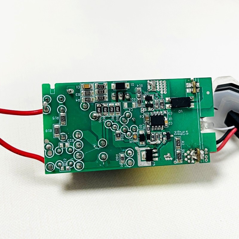
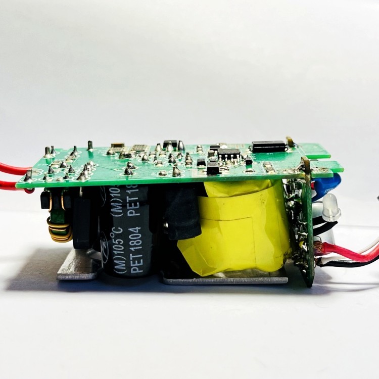
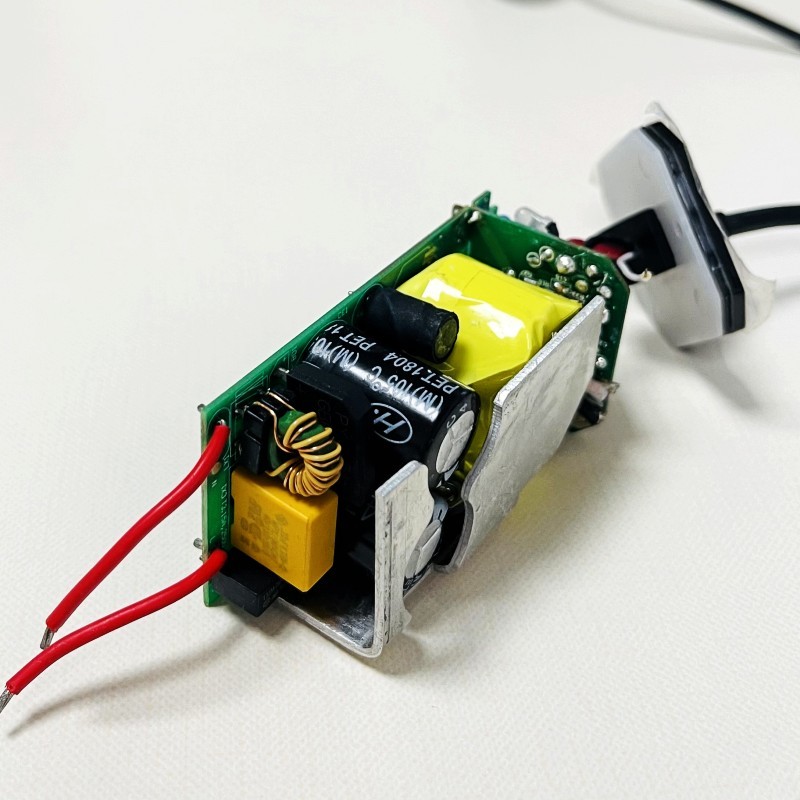
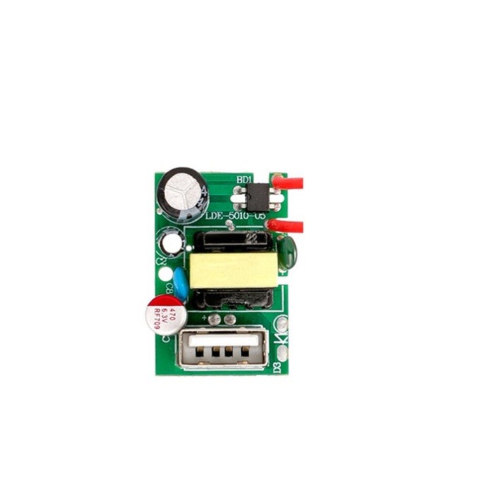
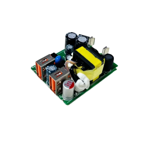
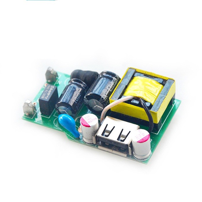
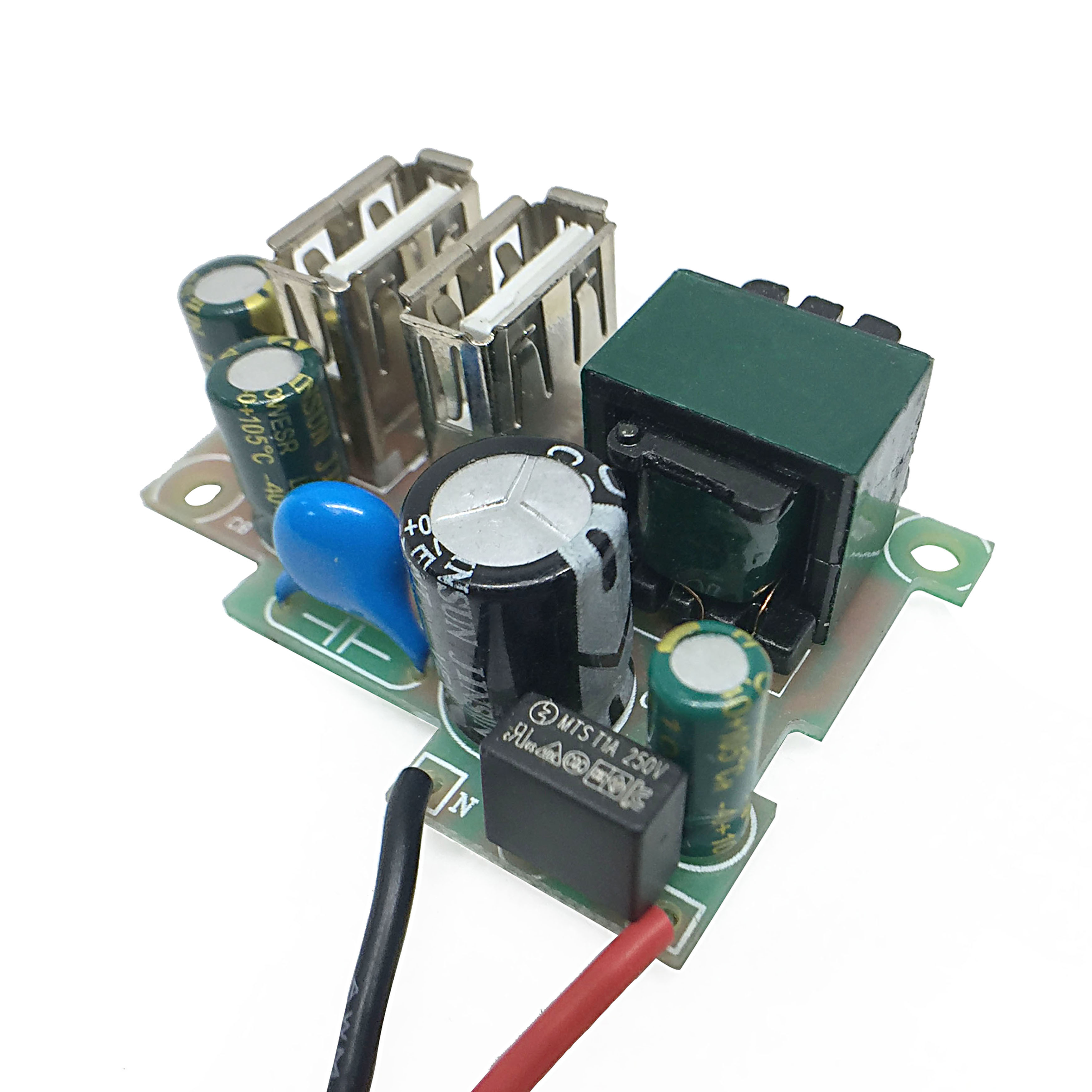
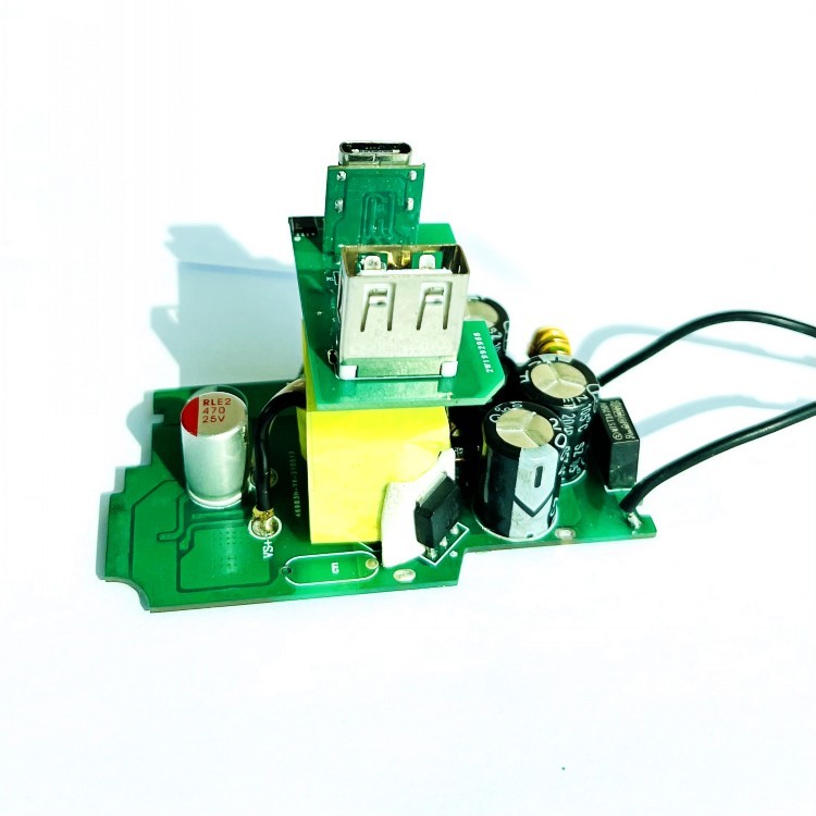
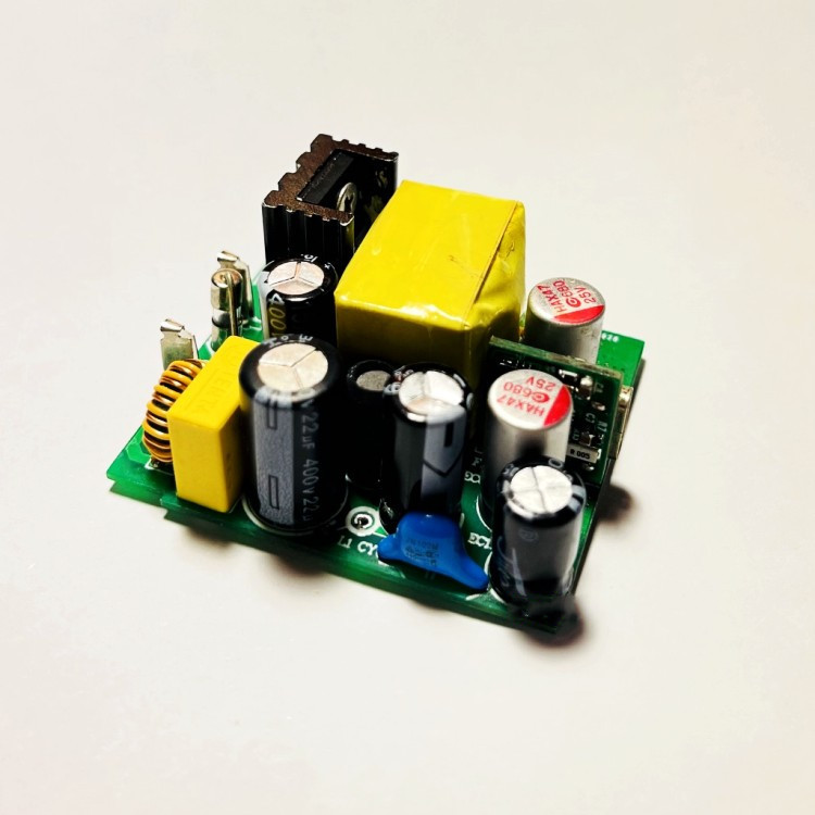
60W Module Board Power Supply Module Printed Circuit Board Assembly
Overview
With a 100% increase in operating frequency, an innovative smart design, and an upgraded circuit board structure, PD3.0 technology makes our latest PD60W Power Supply Modulesmaller without sacrificing a drop of power.Switching Power Bare Board Circuit USB-IF Certified power adapter ensures safety with a dependable construction and over voltage, current and temperature protection and industry safety certifications: ETL, FCC, CE.
Description:1. Input voltage: AC 100V-240V 50-60Hz2. Output voltage: DC 5V 9V 12V 15V 20V3. Output current: 3A4. Output power: 60W5. Operating temperature:-30 – +85℃
Specification:
| Specifications | |
| Model No | APS-CB2020 |
| Applications | Wall Charger, Fast Charger, Quick charger 3.0 ChargerPD charger, Travel adapter, Universal Adapter, Multi USB chargers, Type C charger and so on….. |
TechnologyFast Charge, QC 3.0 if you needInput
AC100V-240V(Standard)
Output60WWIRE 5V 3A/9V 3A / 12V 3A/15V 3A / 20V 3A Efficiency(Full load)85-90%Safety Protection
Over Voltage Protection
Over Current Protection
Short Circuit Protection
Over Hot Protection
Burn in100%MTBF5000Hours
Lead time:
| Quantity(piceces) | 1k~30K | 30K~50K | 50k~100k | over 100k |
| Lead time | 20 work days | 30 work days | 40 work days | Negotiation |
Shipping :
1. DHL / UPS / FedEx / TNT , Door-to-Door.2. By Air or by Sea , for FCL; Airport/ Port receiving.3. Customers Specifying Freight Forwarders or Negotiable Shipping Methods.4. We choose the best and safe packaging material to make sure your orders won’t be damaged
during delivery.
Why Choose us
APS offer Electronics Manufacturing Services (EMS) Company in Shenzhen since 2010. With more than 100 highly skilled employees, providing one-stop service of PCBA, including PCB development, PCB manufacturing, component purchasing, assembly, programming, functional test, box-building, and so on.
1. 10 years OEM&ODM factory experiences in Power solutions.
2. Licensed MFI Apple factory
3. Specialized in Mobile Phone Accessories,including Apple MFi car Charger, iphone charger, Wireless
Chargers, wall charger, laptop power supply adapters and so on…
4. Strict QC team control quality
5. OEM/ODM service
6. Small MOQ support
7. Quick Delivery Time
8. Warranty 12 months after-service
9. Continul Technical innovation
Any other concerns, welcome to send your request to email.
Your feedback is the most important for us.
Here are some guidelines to be commented on for peer reference. Make the repair work orderly and step by step
Criterion 1: look first, then measure
The circuit board to be repaired shall be visually inspected first, and the magnifier shall be used for observation if necessary
Mainly see:
1. Whether there is any disconnection or short circuit, especially whether there is any crack or adhesion on the connecting line of PCB;
2. Whether the related components such as resistance capacitance inductance diode triode are disconnected;
3. Whether someone has repaired it? Which equipment has been moved? Whether there are problems such as faulty welding, missing welding, wrong insertion, etc
After removing the above situation, first measure the resistance between the power supply and the ground of the circuit board with a multimeter. Generally, the resistance of the circuit board should not be less than 70 Ω. If the resistance is too small, it is only a few or a dozen ohms. It means that measures must be taken to find out the broken down component equipment if there is component equipment on the circuit board that is broken down or partially broken down. The specific method is to power up the repaired board (note! At this moment, it is necessary to find out the component equipment of the board The voltage value and positive and negative polarity of the working voltage shall not be connected wrongly or added higher than the working voltage value. Otherwise, the circuit board to be repaired will be damaged! The old fault has not been eliminated and new defects have been added!!) the temperature of each equipment on the circuit board shall be measured by the point thermometer, and the fast and high temperature rise shall be regarded as the key problem object
If the resistance value is normal, then measure the resistance and capacitance devices on the board with multimeter. The purpose is to ensure that the measured devices are normal. If you can use general test tools (such as multimeter, etc.), do not complicate it
Guideline 2: first outside, then inside
If the situation allows, it is better to have a good circuit board as the same as the board to be repaired as a reference. Then use the dual port VI curve scanning function of the tester to carry out a good and bad comparison test on the two boards. The comparison test point of the beginning can start from the port of the circuit board; Then, the comparison test from the outside to the inside, especially for the capacitor, can make up for the defect that it is difficult for the multimeter to measure the leakage of the capacitor on line
Rule 3: easy before hard
In order to improve the function of the test, some skill processing should be done to the repaired board before the online function test of the circuit board to minimize the impact of various disturbances on the test process. The specific measures are as follows:
1. Preparation before test
Short circuit the crystal oscillator (make sure that the four legs of the crystal oscillator are the signal output pins that can be short circuited. Remember that in general, the other two legs are the power pins. Do not short them!!) for large capacity electrolytic capacitors, weld the next leg to make them open. Because the charging and discharging of large capacity capacitors will also cause disturbance
2. Test the equipment by sweeping
In the process of on-line test or comparative test for the equipment, please directly acknowledge the test results and record the equipment that has passed the test (or is more normal). The equipment that has not passed the test (or is more out of tolerance) can be retested. If it still hasn’t passed the test, you can first acknowledge the test results. Such a test can be continued until the equipment on the board has been tested (or compared). Then you can deal with those equipment that haven’t passed the test( Or more out of tolerance) equipment
For the equipment without function on-line test, some test instruments also provide a kind of irregular but more useful treatment method: because the power supply of the test instrument to the circuit board can also be applied to the corresponding power supply and ground pin of the equipment through the test clip, if the power supply pin of the equipment is cut, the equipment will be separated from the circuit board power supply system
-
12W USB Wall Socket PCB Assembling 5V 2.4A AC T...
-
AC DC 2 QC3.0 USB 18W PCB Electronic Circuit Board
-
5V 3A USB Wall Socket PCB Assembling USB A Fast...
-
10W USB Wall Socket PCB Assembling Bare Circuit...
-
5V 9V USB Wall Socket PCB Assembling 12V 15V 20...
-
45W PD 3.0 Printed Circuit Board Assembly 5V 9V...